Machining Workflows keeping track of notes while making parts
Table of Contents
1. Water Jet Cutter
1.1 Project Aluminum Part
1.2 CAM
1.3 Machine Operation
Save as dxf file the sketches made in Fusion.
Login to the computer and double-click to open the dxf file with th default OMAX software.
Erase redundant line by Right Click ==> Select ==> Cursor and press Delete.
If you have holes, decrease the Size by Selecting each one individually and then pressing Size and deceasing
the Scale factor.
Assign Qualitties by Right Click ==> Quality and Etch for the holes. (Do not do Select first and then Quality)
Click immediately on semi-circle outlines of holes and they should become grey.
Deselect All
Assign Qualities Right Click ==> Quality ==> Number 3 for the Outline
Click immediately on each line
Now, you have to check of there are any mistakes in the outline like duplicates etc.
On the right side, Click something .... and then OK You should receive zero's, of not press OK for the design
to be fixed automatically.
Then press Lead I/O on the lower left side of the panel..
Then, on the right side of the panel click on the something related to automatic default planning etc and then oK.
This will generate a file colored as blue in teh default location from where you opened the initial dxf file.
Double click on this file and it will open with the machine console.
Input stock thickness.
Click on the starting point of the toolpath.
Zoom in to each hole and check if there is any black area. If yes, this means that there is going to some
material left-over. You want them to be red and also you want the etching to start form the inside towards
the outside. If there is any problem, go back, fix the size, generate again the toolpath (blue file) and load
it to teh machine. CHeck again! Fix your stock on the machine bed and secure it carefully so that there is
no wobbling.
Jog the head to the starting point of the toolpath.
Zero the toolpath by pressing the lower zero. The upper one is the machine zero. (Ask Sara when she is using
the machine zero..she mentioned that case but I forgot.
Make sure there is the plastic container is full of sand.
Check by eye if the toolpath might cause interference of the plastic tubing with any of the clamps or weights
so that you won't have any unpleasant scenarios during machining.
Now do not forget to zero Z. You have to make the machine got to Z zero right before start machining. It
doesn't go there automatically.
Rise water right below the holes on the wall by using the jog under PC display.
Press Start Machining.
You can always press PAUSE use the fresh water and inspect if your job is going well.
After job is done, clean, close software and log-off.
2. ProtoTRAK SMX CNC Mill
2.1 Project: Aluminum Part
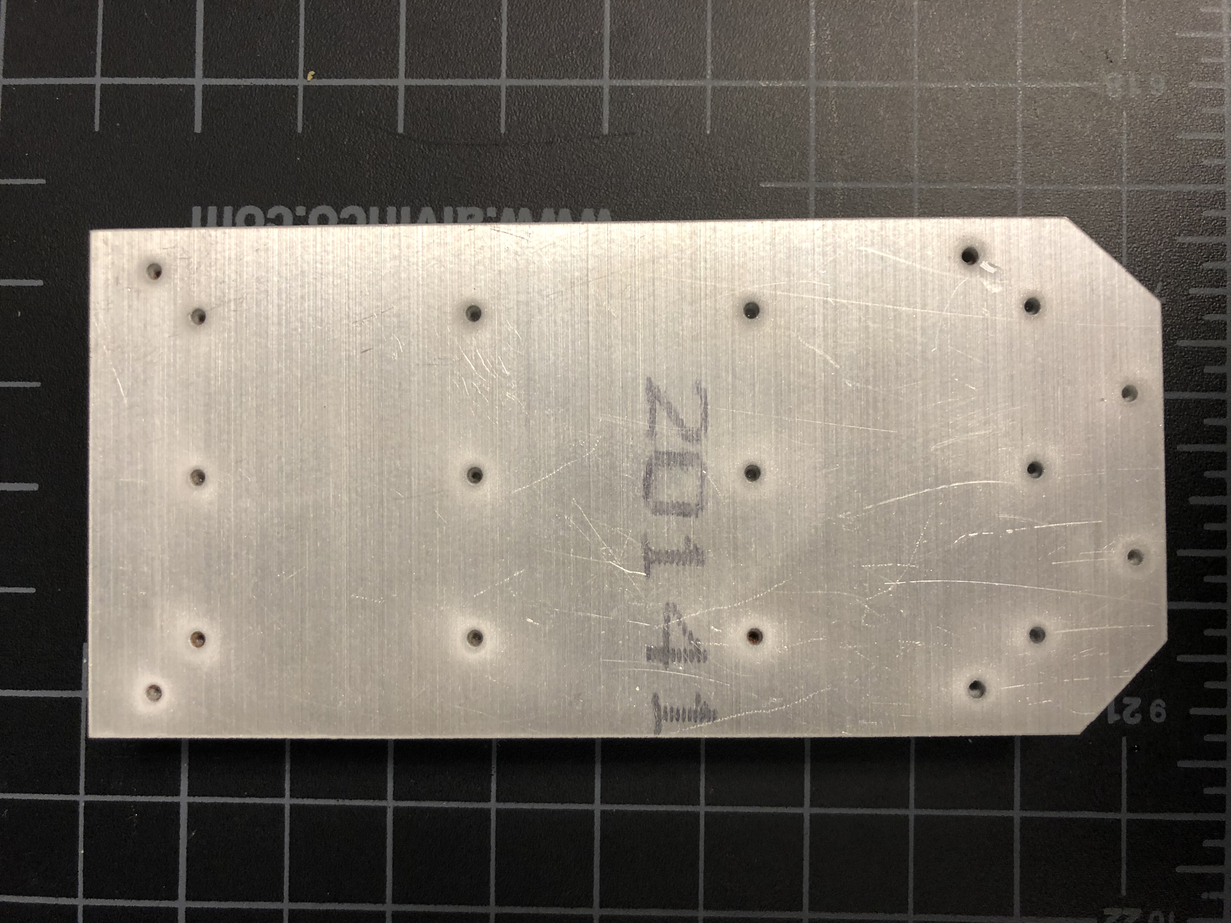
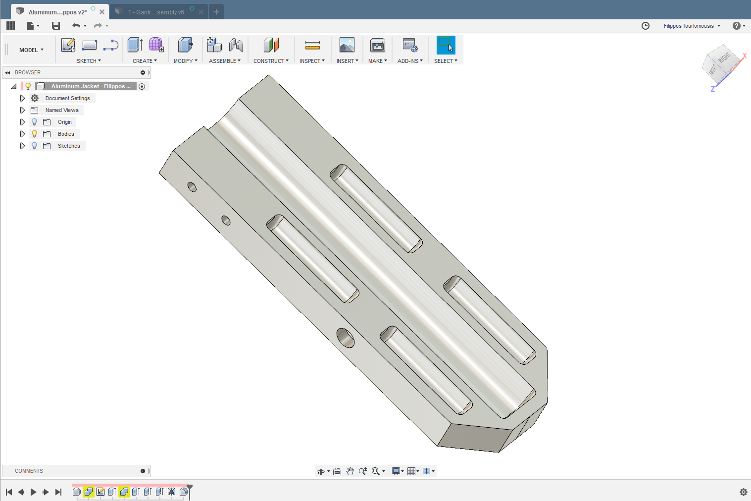
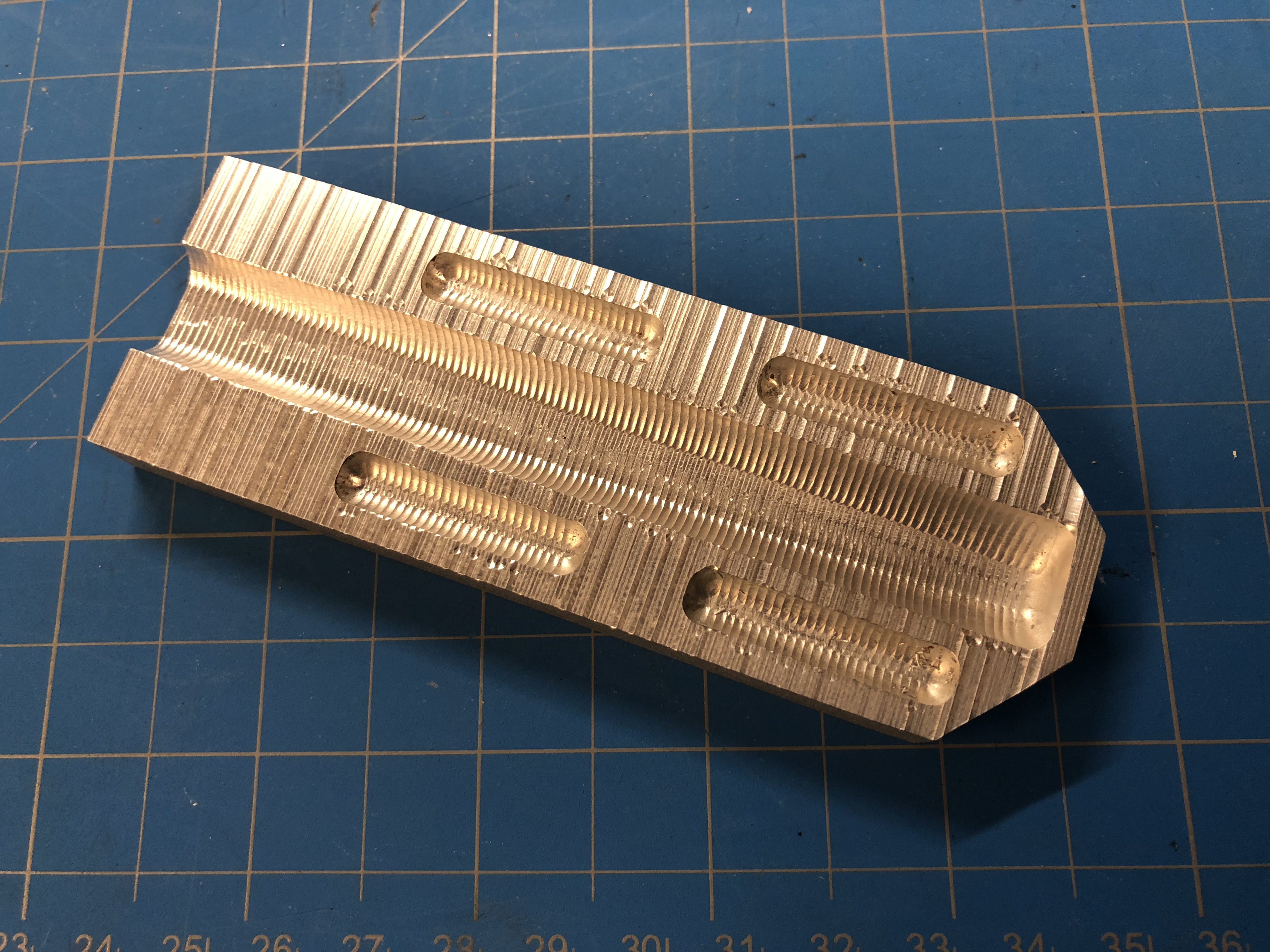
For my electrowriting machine, I need to make a heating jacket that can host and maintain the syringe containing the thermoplastic polymer that I aim to print at a specific temperature. I started designing the jacket by sketching in detail the interface of the glass syringe that I am using. Sketching the profile and then doing a Revolve operation in Fusion resulted to a very complicated model that offcourse could not be machined. Lesson learned for one more time... Design philosophy for 3D printing cannot be applied when you aim to make an aluminum part using CNC machining. After discussion with Sam about CNC machining and what I can make, I decided to split the jacket in 2 identical parts containing pockets for the syringe barrel and 3 small electrical heaters. In this way, I could probably use a single ball end mill to run the whole job. In any case, below you can see the 3D model of the identical jacket parts and a machined part that looks extremely ugly! Long story short the disappointing outcome originates from my CAM workflow. I should be able to get beautiful aluminum machined parts. So I decided to use Fusion to do the CAM and document my effort to learn CAM and CNC machining.
2.2 CAM with Fusion
Apparently everyone at CBA knows and uses Fusion's CAM module except me. I started learning how to use it by auditing the
following tutorials.
Autodesk's Beginner CAM tutorials
or click here and then choose the appropriate category.
Deep Dive CAM tutorials by Brad Tallis:
Fundamentals(pt.1/4)
2D CAM (pt.2/4)
3D CAM-Machining (pt.3/4)
Part I: Fundamentals
Cloud Libraries:
You can enable them under Preferences and CAM.
Then, you can find them under Manage or in the Data panel under Libraries and Assets and CAMTools.
Under Assets you can find CAMPosts and Templates, where you store Post Processors (what is that? we are going to
learn that later...)
Thread Milling:
- single vs multi-threaded tool
- radial stock to leave: (major-minor diameter)/2 for bore
- Later you can right click and edit the expression after you have created a thread mill, then although the
thread milling operation is a 3D operation, you can find it under 2D.
Hold Control when you don't want your Sketch to be referenced/related to a previous sketch
also Project is awesome when you want to create fixtures/jackets etc.
adding a coordinated system at different locations and make sure positive axis in your program is the same
with positive axis direction in your machine. For example, positive z is when your spindle is moving away from the table.
Part II: 2D CAM
2.3 Machine Operation
This is my favorite machine! It is a Vertical Milling Machine NC X Y Z axis.
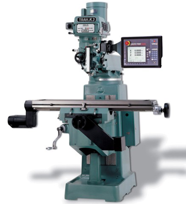
Here is the tool's Gitlab page.
Tom and John have done wonderful job maintaining it over the years. Tom trained me on this machine and below are
all the notes
gathered from this training and the times I used it in order too make the complex aluminum part described above.
First of all you shouldn't rely only on training. Every machine has an operation manual like this one.
You can find it HERE.
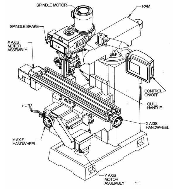
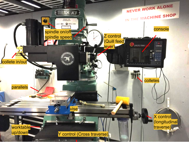
By Reading the manual, I was able to clarify a couple of things that caused me confusion such as the terminology
for the different parts of the machine:
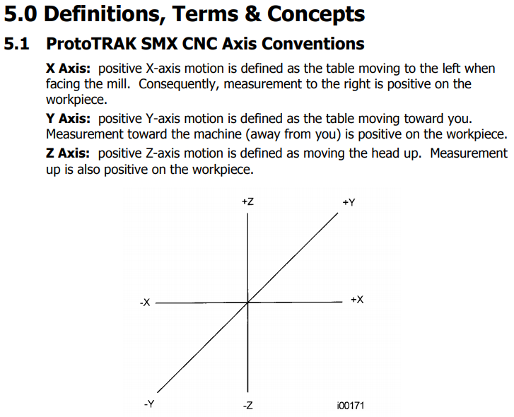
and axes conventions:
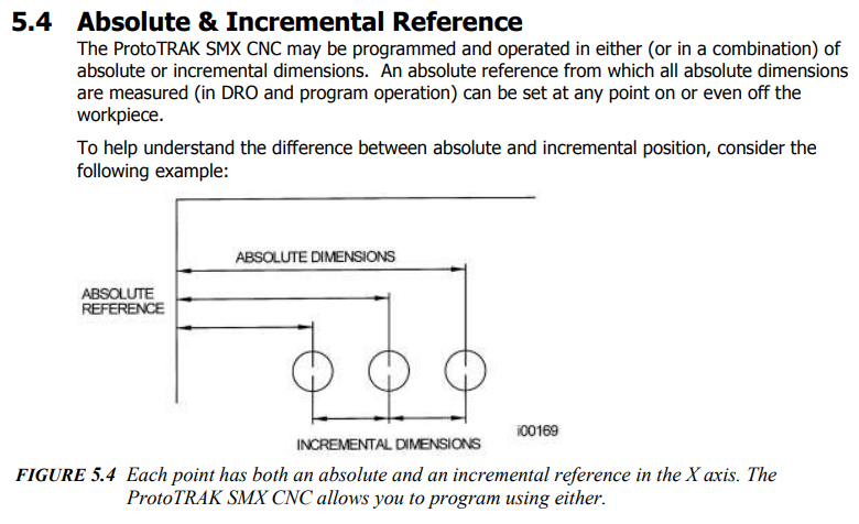
 position referencing:
and tool diameter compensation:
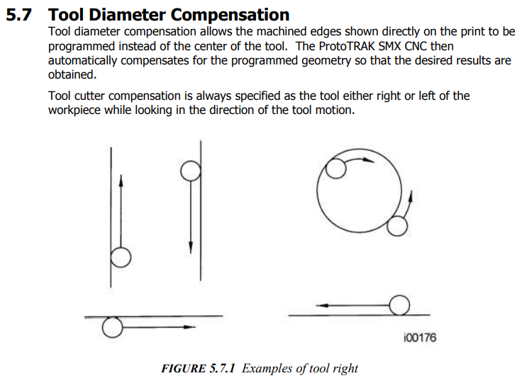
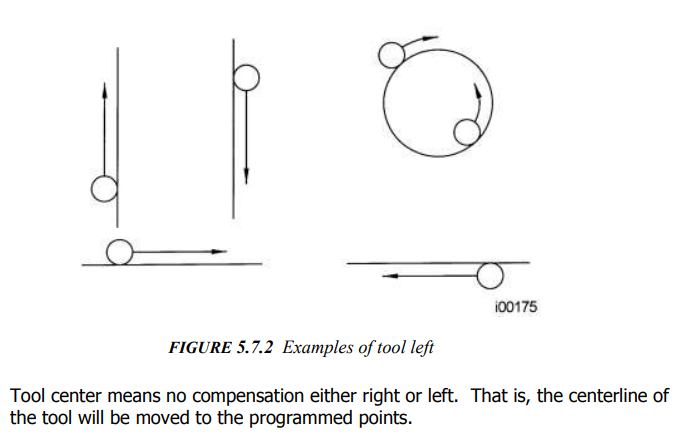
These two images are particularly useful for understanding all the protocol steps:
MACHINE PROTOCOL OPERATION:
1) Material Setup
Place pre-cut aluminum stock (note that the outline of the aluminum part was cut on water jet, cutting with this
machine may require a different setup) on parallels. Crack it down using the vise handles to hold the material
firmly. There are parallels of different height on the table right next to the machine. Ideally the material
should be a hair above the top of the clamp.
2) Zero X-Y axes using Edge Finder
Before running a part, you must establish the position relationship between the part and quill. That is, you
need to identify where the part is on the table relative to the tool or quill centerline. This is done by using
an edge finder or dial indicator to move the table so that the part program absolute zero is under the quill
centerline. ABS SET this position as absolute zero in the DRO mode. In addition, load the tool for Event 1
and position it at Z absolute zero. If this is impossible, position the tool some known distance above absolute
zero and ABS SET this dimension. Tool Offset: is the selection of the tool offset to the right (input 1),
offset to the left (input 2), or tool center--no offset (input 0) relative to the programmed edge and
direction of the cutter movement.
- Move handle to wake up the machine.
- Move bed away from spindle.
- Find the edge tool in the drawer on the table right next to the machine.
Choose the correct collette (the one that matches the edge tool diameter) from the holder hanging on the right
of the machine.
- Insert the edge tool inside the colet.
- On the console, click Mode to go to DRO mode so that you can move the bed by the black handles.
- Bring z all the way up using the 3 pronged handle (quill feed lever).
- Push colet in and press the IN button upper left tto lock it. These are pneumatics and it will sound
like a jackhammer going off.
NOTE: This won't work unless the z axis is all the way up. The large silver shaft should be retracted all
the way up.
BE CAREFUL not to get your finger caught in the colet. Use a paper towel to hold it up when you hit
IN.
- Move table with black handles around for X,Y. Zero X axis by bringing the colet outside the side which is
across the y axis when you facing the mill. Turn on the spindle and move it towards the side until it bends
and then slowly bring it back.
- Then, set zeros : X button ==> ABS SET button
Y button ==> ABS SET button
- Lift the z-axis and move X and Y manually towards the part by half the diameter of the edge tool (0.1 mm).
- Then, again SET ZERO : X button ==> ABS SET button
Y button ==> ABS SET button
Now the center of your tool right above the the lower left corner of your mounted piece.
You can check by pressing the softkey corresponding to RETURN ABS ZERO.
4)Test your Toolpath File on air
- Do that by tricking the machine and setting Z axis zero right above the upper surface of your
stock-piece.Follow Steps -...- shown below for running your file
5)Load actual tool
6)Zero X and Y axes
7) Run trial
Tip: Before zeroing Z on the material, set Z 0 above the actual material surface to do an air cut.
Follow the loading and running cam file steps and then come back and zero Z.
8) Zero Z axis
- Put a strip of butcher paper on material.
- Move paper around while bringing head down until the paper gets stuck between endmill and material.
- To zero the Z axis: Z -> ABS SET
9) Load Toolpath - CAM file
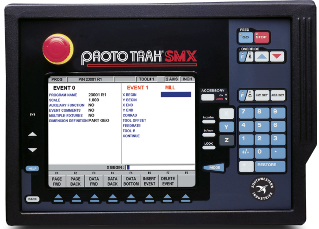
The toolpath file is generated with the CAM Fusion workflow previously described. To open a program file from a
storage location, press the OPEN softkey from the Program In/Out Mode screen. The ProtoTRAK SMX CNC will always
default to the last folder you had open. Find the file using the softkeys as described above in the section on
basic navigation. When a program file name is highlighted, press the LOOK hard key to see a graphical
representation of the part program. The graphics are not a precise representation of the tool path, but should
be very handy in helping to identify a file before opening. In addition to the basic parts of the screen
described above, two additional parts of the screen appear in the open operation: File Name: - Displays the
name of the file that is highlighted from the list. Open As: - lists the formats for which the file may be
opened. The default is .PT4. Two additional softkeys appear: OPEN FILE: Opens the highlighted program file and
puts it in current memory. Only one file may be in current memory at a time, if one is there already, a warning
message will appear before that file is overwritten.
RETURN: Returns to the Program In/Out Mode screen. When the open operation is finished, the system will return
to the Select Mode screen.
As an aid to finding the file you want to open, the ProtoTRAK SMX allows you to look at the part graphics before
opening. Simply select the file and press the LOOK hardkey. The screen will show the part graphics. Press LOOK
again or RETURN to revert back to the Program In/Out screen.
In short:
Insert thumb-drive
MODE -> PROG I/O -> OPEN
DATA_FWD to find file. Open file.
It will ask if it is okay to override mem. Hit Yes.
8) Setup Z retract
(keep head about 2.5 inch of big shiny cylinder visible)
MODE -> SETUP -> REF POSN -> Z RETRACT -> ABS SET
If z-retract isn’t set correctly it will complain when you hit go. Try raising z and do abs set again.
9)Start the job
MODE -> RUN (verify it says 3 axis on the top. if not press SYS to make sure it is in 3
axis)
START
It will ask if tool is properly set?
Hit RESUME for yes.
Hit GO button (under feed).
The head will move to x0, y0 but not cut.
Turn spindle on to 2 (turn it off to 0 to make sure that the rotation is clockwise).
Set speed to 4200rpm (for 0.25in mill on 6061 aluminum) on the 1930s looking dial with the silver handle on
the right. Hit GO again. This is it.
And we are off:
Add plenty of fluid (motor oil or the blue coolant) and use compressed air nozzle to clear chips.
10) Finishing up
Cut out the tabs with a dremel if you have tabs.
2.4 Things to remember
Things to check out
in the machine:
- Z retract is the position at which the machine is moving to the home position and the starting point to
toolpath- this is important if you have fixtures with certain height that you want to avoid
- any z-movement in the toolpath shouldn't be larger than the Z retract value set in the machine. Account for
stock thickness and cut length of the tool
-is your piece aligned?
- have you zeroed the Z axis correctly?
in CAM:
- always check your the stock origin and dimensions before you send toolpath to the machine. You might have
changed the model or you might want the stock origin/dimensions to match the dimensions of the part that you
have already milled for certain reasons (moving holes to other positions etc.)
- if you drill holes along with flattening and cleaning cut-outs think twice which operation you are going to
do first. Maybe you want want to do the flattening and cleaning cut-outs first in order to align correctly your
part on the machine. Then drill holes to be perfectly aligned to edges of your piece. In that case what should
be the stock origin? Maybe you should measure the dimensions of the flattened and cleaned part, update your model
and then generate the toolpath
correcting mistakes:
- if you made a mistake in any cleaning cutout operation because you didn't align correctly your piece on the
machine bed, you can correct it by increasing the stock dimensions in this side, generate the toolpath and zero
your machine to the outer side. The additional stock thickness in the software should be slightly larger of the
length difference of the outer side to the inner side and offcourse don't forget to align your part correctly.
Lastly, you can choose individual contour line segments to confine CAM operations in certain areas by ALT+left mouse
click.