Toolpath Planning with Fusion 360
Table of Contents
1. Fundamentals of CNC Machining
1.1 Overview of CAD-CAM Process
1.2 Shop Safety (just a reminder!)
->Dive in Toolpath Planning<-
MAS.865 2018 HOW TO MAKE SOMETHING THAT MAKES (ALMOST) ANYTHING
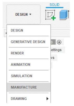
1. Fundamentals of CNC Machining
1.1 Overview of CAD-CAM Process
The general workflow to go from CAD model to machined CNC part is:
1. Begin with CAD model.
2. Establish Job parameters including CNC coordinate system and stock shape/size.
3. Select CNC process.
4. Select cutting tool and machining parameters.
5. Select driving CAD geometry.
6. Verify toolpath.
7. Post Process.
8. Transfer G-code program to CNC machine.
9. Set up and operate CNC machine to make part.
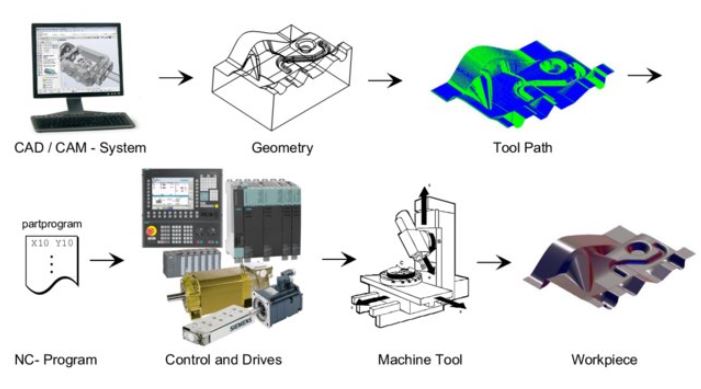
Process chain from CAD/CAM-system to workpiece.
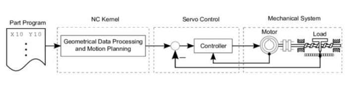
Control structure of one axis in a CNC machine tool.
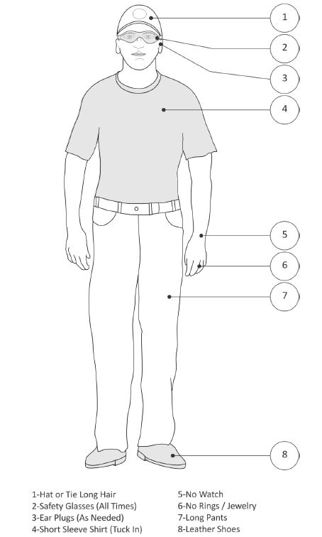
1.2 Shop Safety
Just a reminder!
1.3 CNC Tools - Terminology
End Mills
Goals:
- List the most commonly used CNC tools.
- Determine spindle rotational direction.
- Interpret a chip formation diagram.
- Define chip load.
- Distinguish between climb and conventional milling.
- Compute cutting speeds and feeds for a specified tool, material and operation using reference tables.
A wide range of tool types and configurations are available for CNC milling machines. Discussing every type,
variation and use is beyond the scope of this recitation. The most commonly used tools for prototype and short run
production machining will be introduced. Any tool supply catalog will list many others. Here we are:
- End mills (Flat, Ball, Bull and Chamfer) Face mill
- Corner Rounding tools
- Slot Tools
- Spot-‐Center Drill
- Twist Drill
- Tap
- Reamer
- Counterbore
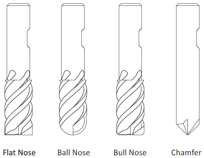
Flat nose mills are used for milling 2D contours and pockets.
Ball nose mills are used for 3D milling.
Bull nose end mills have a radius corner. They are used to create a fillet on the bottom of a wall.
Because they are sturdier than an end mill they are also sometimes used for roughing operations.
Chamfer end mills have an angled nose used to create a chamfer or to de-‐burr parts.
Number of Flutes
Milling tools usually have either two or four cutting flutes. Two flute cutters provide more chip clearance
when milling in close areas. Four flute mills are more rigid, can be fed faster, and are preferred when greater
chip clearance is not required, such as when milling an outside contour.
Cutting Tool Terminology
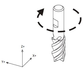
All tools (except left-‐handed taps) rotate clockwise (M3) when viewed from the machine spindle looking down at the part.
Cutting tools remove metal by shearing action as illustrated in the Figure below. As the tool advances into the material it causes a small amount of the material to shear away, forming a chip.
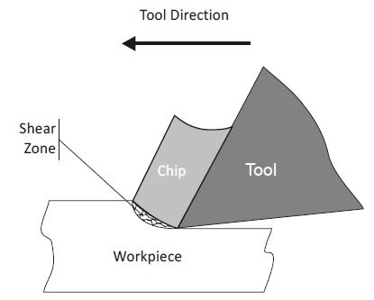
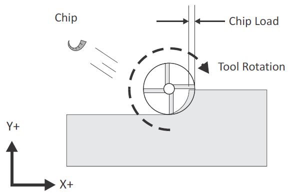
The thickness of material sheared away by each cutting tooth is called the feed per tooth, or chip load. As the chip is ejected from the work area it carries with it some of the heat generated by the shearing process.
One of the best ways to validate cutting speeds and feeds is to observe the chips created by the machining process. Chips should be curled and may change color due to heating. After gaining some experience machinists are able to adjust cutting speeds and feeds based in part on the size, shape, and color of chips and on the sound produced by the cutting process.
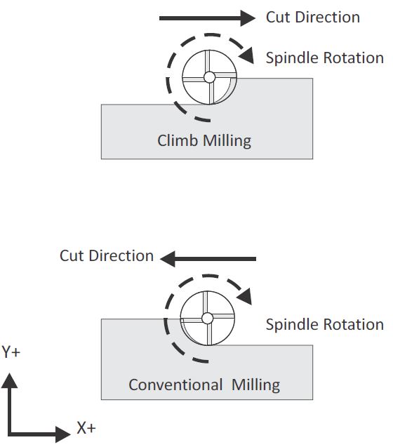
Milling tools can advance through the material so that the cutting flutes engage the material at maximum thickness
and then decreases to zero. This is called Climb Milling.
Cutting in the opposite direction causes the tool to scoop up the material,starting at zero thickness and increasing
to maximum. This is called Conventional Milling.
Conventional milling is used often on manual machines because backlash in the machine lead screws causes the tool to
lurch when climb cutting. This is not a problem on CNC machines because they use ball screws.
Conventional milling causes the tool to rub against the cutting surface, work hardening the material, generating
heat, and increasing tool wear. Raking chips across the finished surface also produces a poorer surface finish.
Unless specifically recommended by the tool manufacturer for the material being milled, always use climb
milling on a CNC. Climb milling produces far less cutting pressure and heat, leaves a better surface finish, and results in
longer tool life.

2. Fusion 360 Concepts
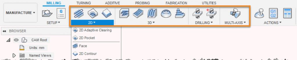
2.1 Manufacture Workspace Overview
The Manufacture workspace contains CAM tools to help you generate toolpaths, program CNC machines, and bring your designs to life. To access the Manufacture workspace in Fusion 360, select Manufacture from the drop-down list.
The toolbar displays the following tabs:

Milling-Turning-Additive
Once a part or assembly file is loaded, the Browser becomes active. The Browser lets you view and modify all
machining-related data in the current part or assembly.
2.2 Toolpath Overview
2D Machining Strategies
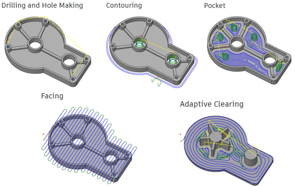
The Manufacture workspace includes a powerful Drill tool for generating drilling, counterboring and tapping operations. The Circular strategy is used for milling cylindrical pockets and islands, while the Thread operation is used for thread milling cylindrical pockets and islands. The Bore operation allows you to bore mill cylindrical pockets and islands by selecting the cylindrical geometry directly. All operations are optimized to minimize tool travel and overall cycle time. Both standard and customized cycles are supported for all point-to-point operations, including spot-drilling, deep drilling with chip break, etc.
With the Contouring strategies, you can easily machine 2D and 3D contours with separate lead-in and lead-out, and with or without tool compensation. Choose multiple roughing and finishing passes and multiple depth cuts for any contour. Machine open and closed contours without c reating additional geometry and eliminate sharp motion with corner smoothing.
The Pocket toolpath is used for machining closed curves both with and without islands. The toolpath starts at the center of the pocket and works its way outward. The entry can be selected anywhere on the model and includes possibilities for plunge, ramp, or at a pre-drilled position. The special high-speed option creates a smooth toolpath and allows you to specify a maximum tool engagement. As a result, the feedrate can be increased significantly, reducing the machining time and tool wear.
The Facing strategy is designed for quick part facing to prepare the raw stock for further machining. It can also be used for clearing flat areas in general.
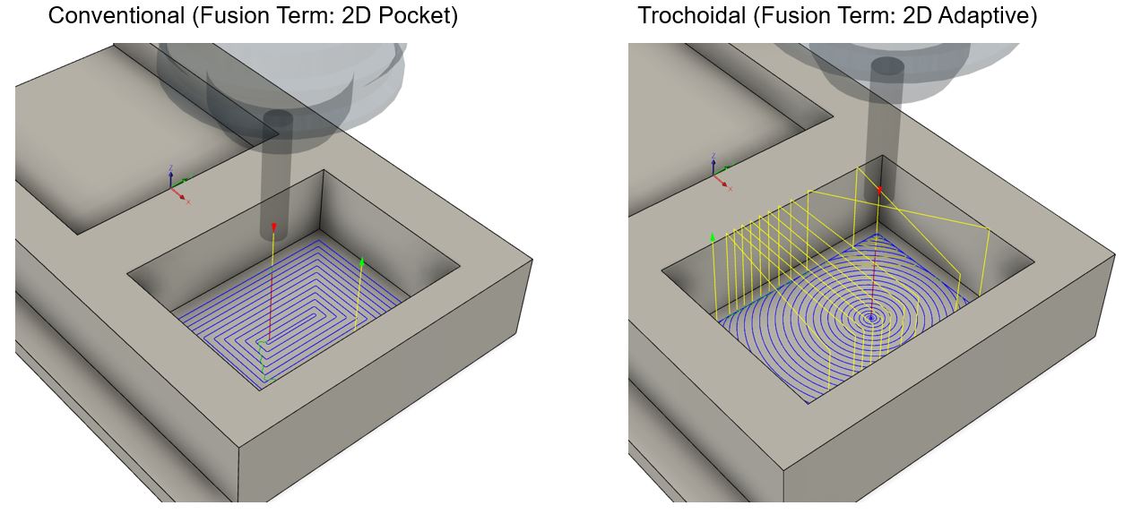
The Adaptive Clearing strategy creates a roughing/clearing toolpath inside closed curves both with and without islands. This strategy avoids full-width cuts by progressively shaving material off the remaining stock. The generated toolpath ensures that the cutting conditions remain constant with a stable load on the tool. As a result, the feedrate can be increased significantly, reducing the machining time by 40% or more which provides improved surface quality and less tool wear.
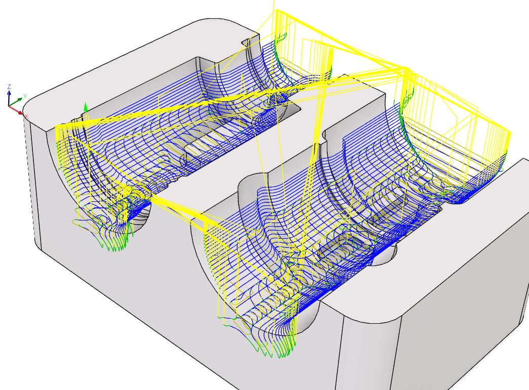
3D Machining Strategies
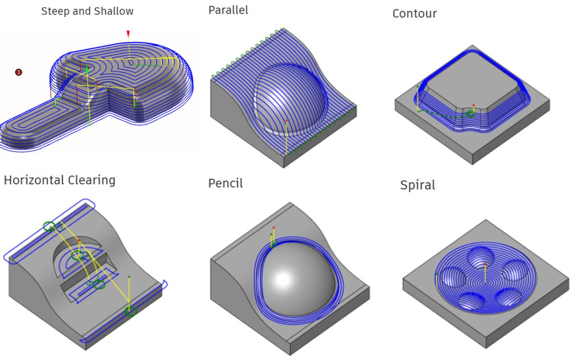
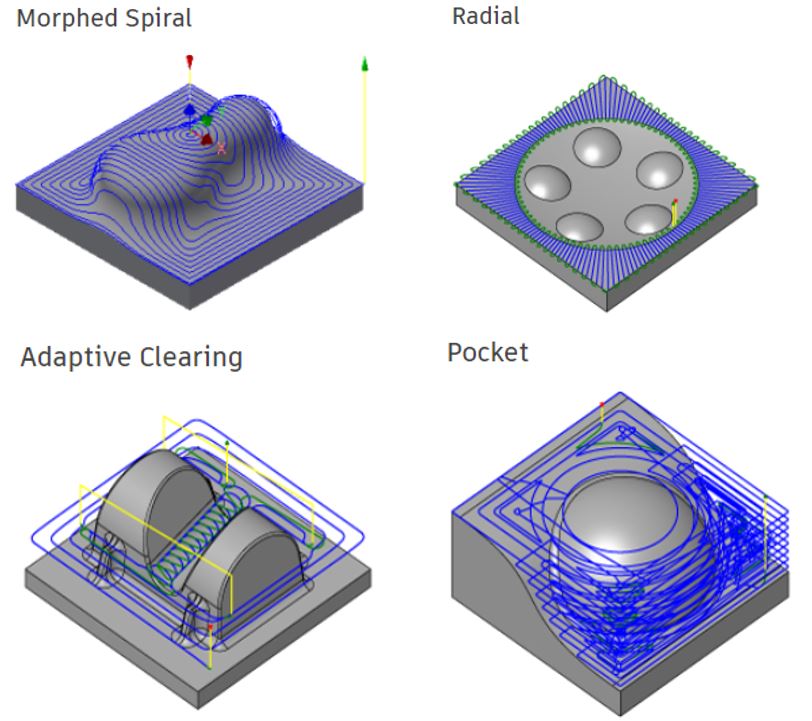
Adaptive Clearing is an innovative roughing strategy that offers significant improvements compared to conventional roughing strategies. The strategy avoids full-width cuts by progressively shaving material off the remaining stock. The generated toolpath ensures that the cutting conditions remain constant with a stable load on the tool. As a result, the feedrate can be increased significantly, reducing the machining time by 40% or more.
Pocket is the conventional roughing strategy for clearing large quantities of material effectively. The part is cleared layer by layer with smooth offset contours maintaining climb milling throughout the operation. To avoid plunging, the tool ramps down along a helical path between levels. To maintain a high feedrate, and thereby reducing machining time, sharp changes of direction are avoided by smoothing the tool motion.
2.3 Postprocessor Overview
A post configuration file (.cps) converts operations displayed in Fusion 360, such as toolpaths and probing cycles, into a language
(usually G-code) that a machine tool can understand. Post configuration files are also known as post processors or posts.
For manufacturing operations to work on your machine tool, you must use a post processor that supports those operations on your specific machine tool.
Where to find a post processor
A selection of generic post processors is supplied with Fusion 360, and they are listed in the Post Process dialog.
Additional post processors are made available for download from the Post Library.
Get help to edit a post processor
If none of the generic post processors are suitable for your machine tool, you can edit a post processor to create one that is.
Visit the HSM Post Processor Forum, to search for help with editing post processors.
3. How To | Tutorials
3.1 Learn the basics
Follow the follow lessons in order to learn the following standard steps in order to generate toolpaths using Fusion 360:
1) Manage your tool library / add your tool.
2) Add your setup, which will include the set of machining operations/toolpaths for making your part.
3) Learn about the Adaptive Clearing roughing strategy, and the differences between 2D and 3D Adaptive Clearing
4) Learn how to use common 2D finishing strategies to create 2D toolpaths.
5) Learn how to create 3D finishing toolpaths.
6) Learn how to run a stock simulation to verify toolpaths before running them on a machine.
7) Convert toolpaths into machine-specific NC code using Post Processing Tools.
3.2 Traditional vs One-way Adaptive vs Two-way Adaptive
Use this tutorial(#1) to understand what one-way adaptive (aka.trochoidal) toolpath is and the differences between traditional and the new Fusion feature about two-way adaptive toolpath.
Use this tutorial(#2) to dive more into two-way adaptive clearing toolpaths.
Use this tutorial(#3) to understand 2.5D machining using a variety of toolpaths.
Use this tutorial(#4) to practive a wide variety of tooolpath strategies in 3D geometries.
Use this tutorial(#5) to understand more advanced 3D machining strategies on 3D parts with intricate geometrical features that reuire tight tolerances.
Check the video link below to see how I generated toolpaths and machined a big monolithic part starting with a very thick stock piece of HDPE.