<br>
##Basic concepts
A good starting point for newcomers in the electronics field looking for what is they must to learn is the flowchart depicted in the image below:
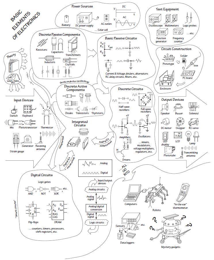
[Symbols and devices](https://roberthart56.github.io/SCFAB/SC_lab/Electronics/electronics_basics/electronic_basics.html)
### Current
- total charge that passes through some cross-sectional area A per unit time
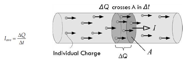
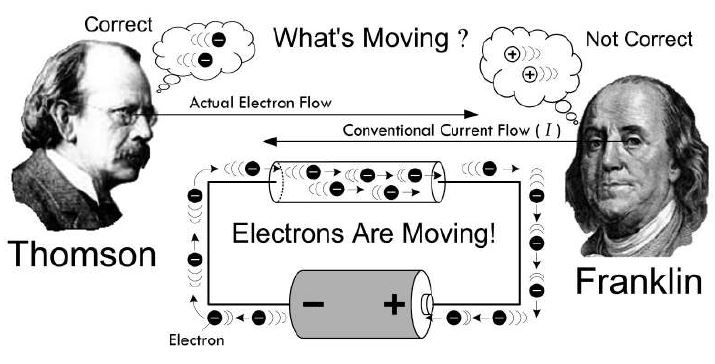
- negative electrons going one way are equivalent to positive charges going in the opposite direction
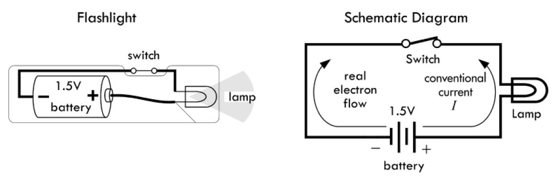
- all basic eqns in electronics such as Ohm's law: V=IR "pretend" that the current I is made up of positive charge carriers
- when we see the term "electron flow", we have to realize that the "convenbtional current flow" is moving on the other way
- Currents in perspective:
- a 100 W light bulb draws about 1 A
- a laptop 2-3 A
- a typical LED 10 mA
- a mobile (smart) phone accesing the web ~ 200 mA
- a sufficient amount of current to induce cardiac/repsiratory arrest around 100 mA to 1A
### Voltage
- [Notes on voltages in circuits](https://roberthart56.github.io/SCFAB/SC_lab/Electronics/electronics_basics/electronic_basics.html)
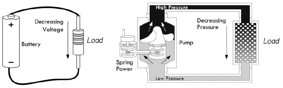
- to get electric current flow between two points you need a voltage across them
- a voltage causes an Electromotive Force (EMF)
- Technical Note: "voltage" known as "potential difference" or just "potential"
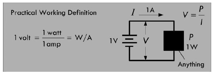
- 1 volt (V) = 1 Joule (J) / 1 coulomb (C)
- two points with a avoltage of 1V across them have enough EMF or "pressure" to perform 1 Joule worth of work
while moving 1C worth of charge between the two points
- for example an ideal 1.5 V battery is capable of moving 1C of charge through a circuit while performing 1.5 J worth of work
- we can define volts in terms of power using the "generalized power law": P = VI
- the above law can be used to determine the power loss of any circuit, given only the voltage applied across it and teh current drawn
- both of which you can measure using a voltmeter and an ammeter
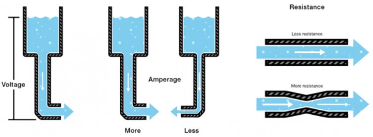
- Water Analogy Explanation of Voltage
### Resistance
- R = V/I
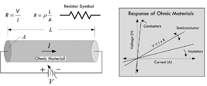
- sometimes we see or we write Ohm's law : V = I x R
- you don't define V in terms of I and R
- you define R ub terms of V and I
- HOWEVER, in electronics we frequently use Ohm's law to predict what V must exist across a known R given a measured current
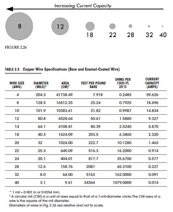
### Wire Gauges
- how the shape of a conductor affects resistance
- doubling the length of a wire doubles the resistance allowing half of the current to flow
- doubling the cross-sectional area ==> opposite effect ==> the resistance is cut in half and twice as much current will flow
assuming for both cases similar applied voltages.
- current density (J=1/A): the rate of current flows per unit area
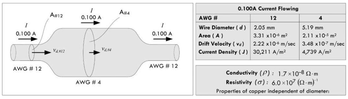
- there is a point at which J becomes so large resulting in wire melt down (laso known as "fusion point")
- NOTE: It is important to select the appropriate wire size for anticipated current levels
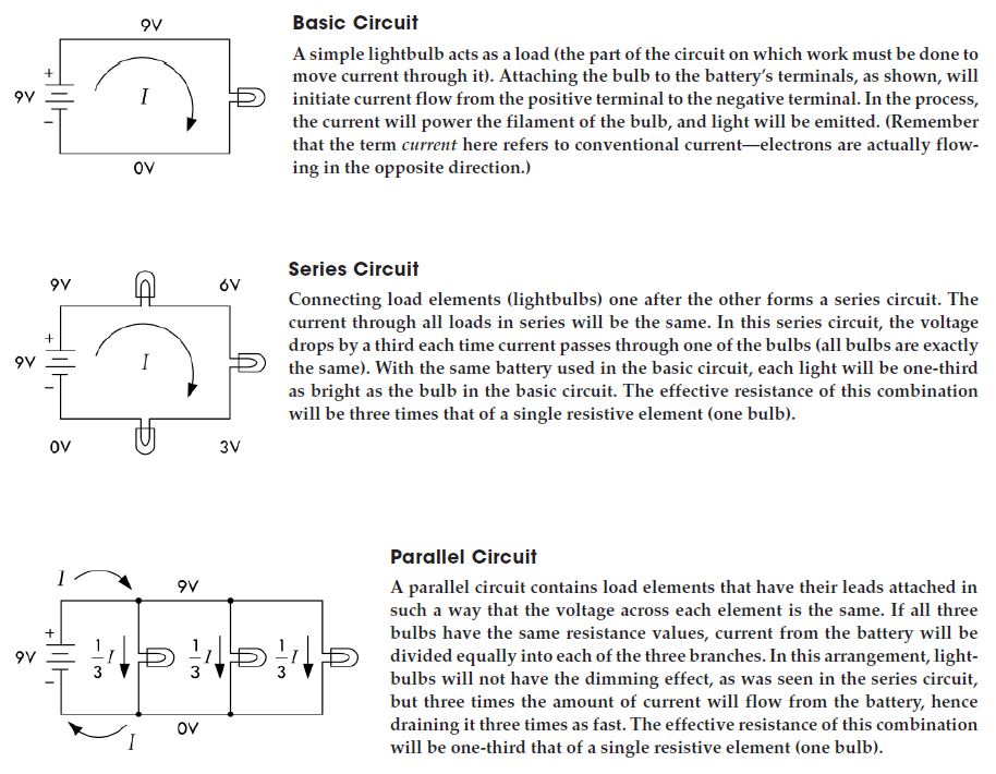
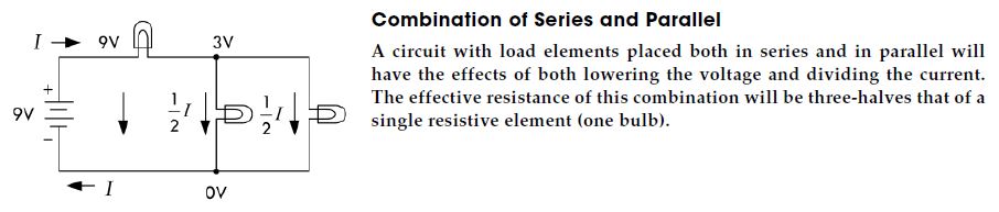
### Circuits
- an arrangement of resistors, wires, or other electrical components (capacitors, inductors, transistors, lamps, motors, etc.) connected together that has some level of current flowing through it.
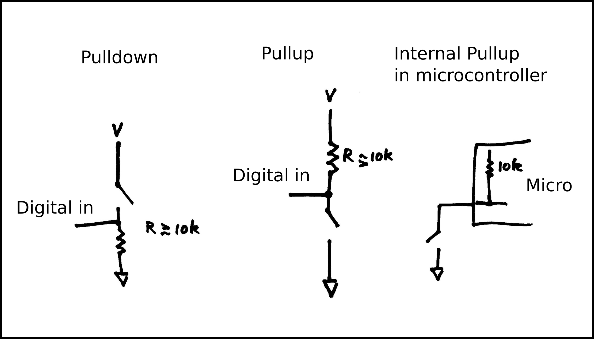
### [Resistors and switches](https://roberthart56.github.io/SCFAB/SC_lab/Sensors/Button/index.html)
### Circuit Analysis
- Goal: volatge and current prediction within a purely resistive powered by a direct current (dc) source such as a battery
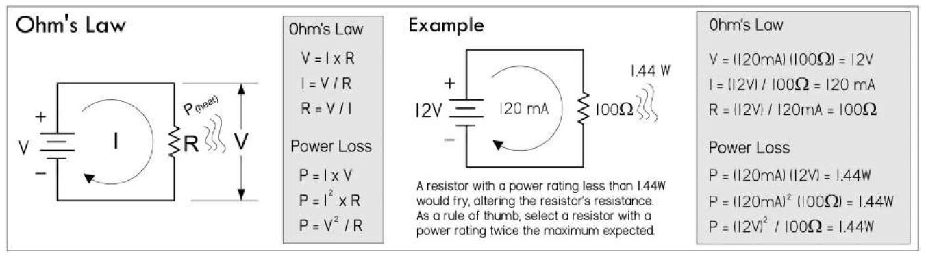
#### Ohm's Law and Resistors
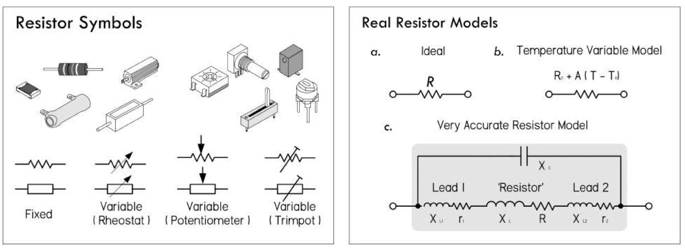
- Resistors: limit current flow or set voltages levels within circuits
#### Example:
- You have a resistor 100 Ohm resistor which is placed across a 12 V battery. How much current flows through the resistor ? How much power does the resistor dissipate?
- Answer:
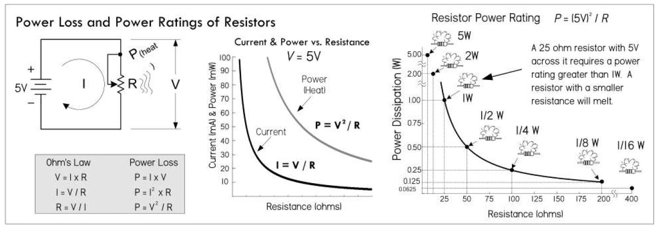
#### Resistor Power ratings:
- how much power does a resitor dissipate?
- max allowable power ratings
- typically resistors in 1/8-, 1/4-, 1/2- and 1-W power ratings
- high power resistors: 2 - 100s of Watts
- NOTE: Always select a resistor that has a pwer rating at least twice the maximum value anticipated
- In our previous examples a 2W resistor would work, a 3-W would be safer
- as resistance decreases, the power raitng o fthe transistor must increase, otherwise you will burn up the resistor
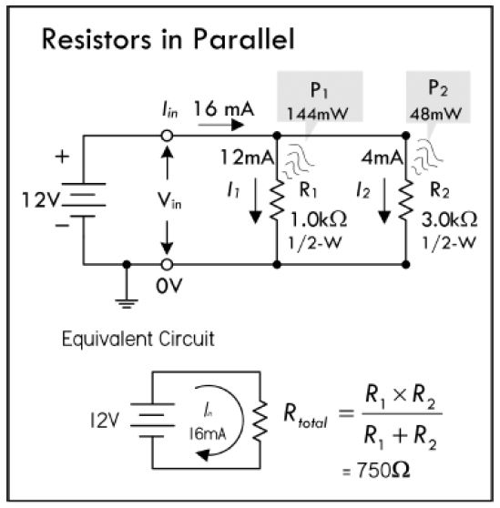
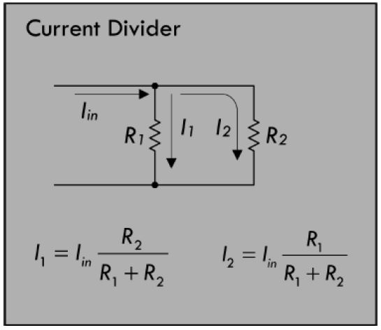
#### Resistors in Parallel
- voltage across each resistor is the same
- current through each resistor will vary with resistance
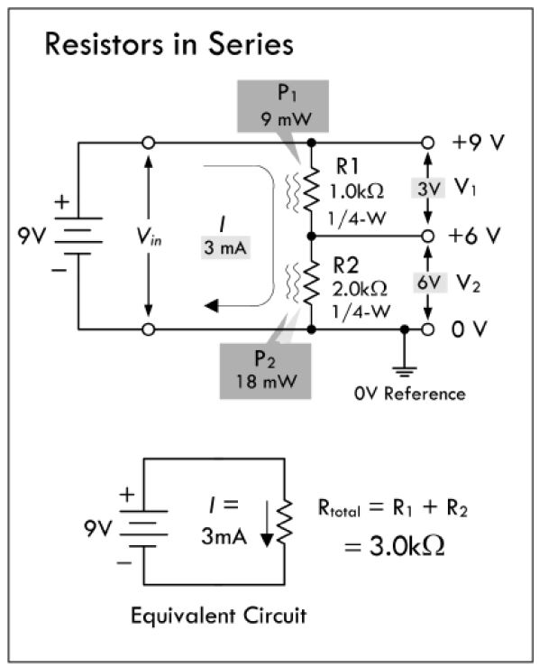
#### Resistors in Series
- total resistance = sum of the individual resistancies
- current flowing through each resistor is the same
- voltage across each resistor varies with resistance
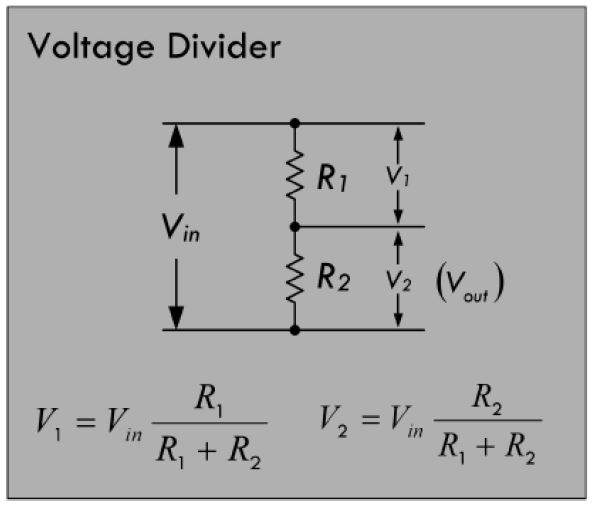
- Examples
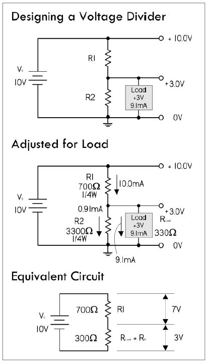
- the input of an IC requires a constant 5V, but the supply voltage you have is 9V. Assumming that the IC draws no current due to high input resistance, you can use directly the voltage divider equation.
- The 10% Rule
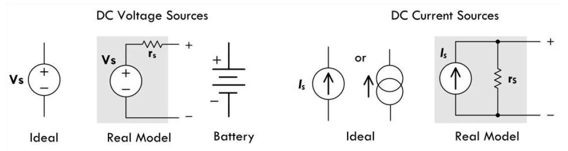
### Voltage and Current Sources
### Circuit Analysis - Important Laws
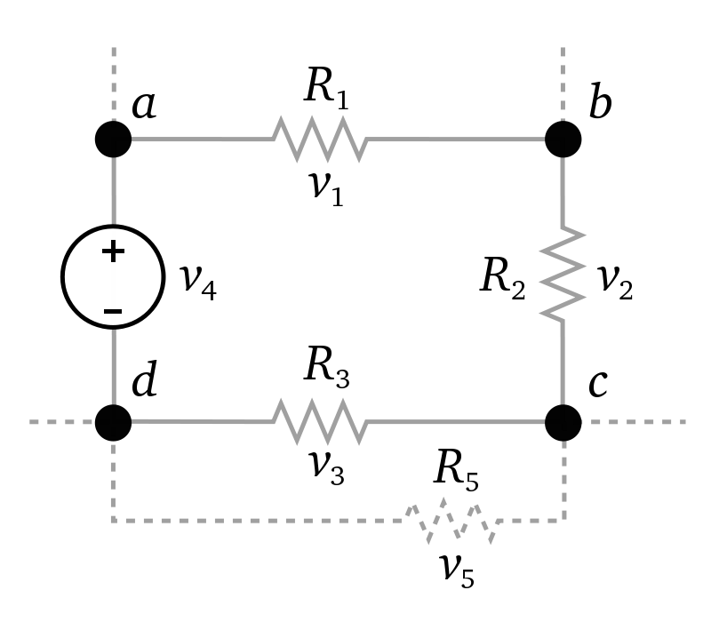
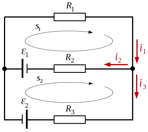
- Kirchoff's Voltage Law (or Loop Rule)
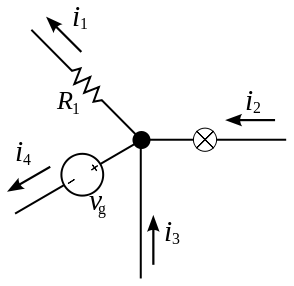
- Kirchoff's Current Law (or Junction Rule)
- Example:
- Thevenin's Theorem
- Norton's Theorem
### Connectors, wires, traces
- headers and connectors. Ribbon cable.
https://learn.sparkfun.com/tutorials/connector-basics#connector-terminology-
- working with wires:
https://learn.sparkfun.com/tutorials/working-with-wire
- Use of breadboards.
https://learn.sparkfun.com/tutorials/how-to-use-a-breadboard
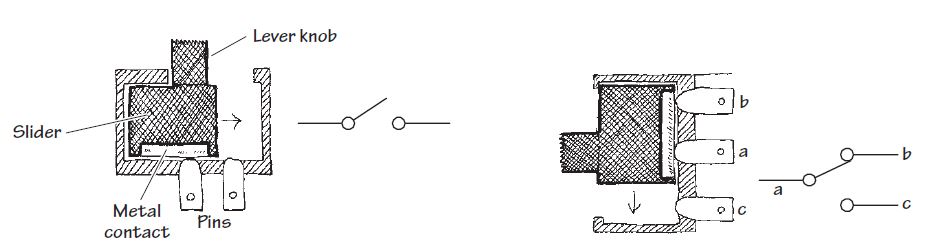
### Switches
- switch: a mechanical device that interrupts or diverts electric current flow within a circuit
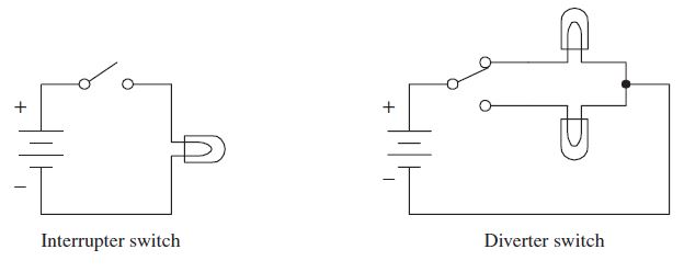
- two slider-type switches shown below
- format of switch description: (number of poles)"P" and (number of throws)"T"
- LEFT: switch acting as an interrupter, SPST
- RIGHT: switch acting as a diverter, SPDT
- A very nice tutorial from Sparkfun on Switches:
https://learn.sparkfun.com/tutorials/switch-basics
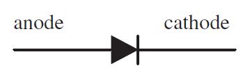
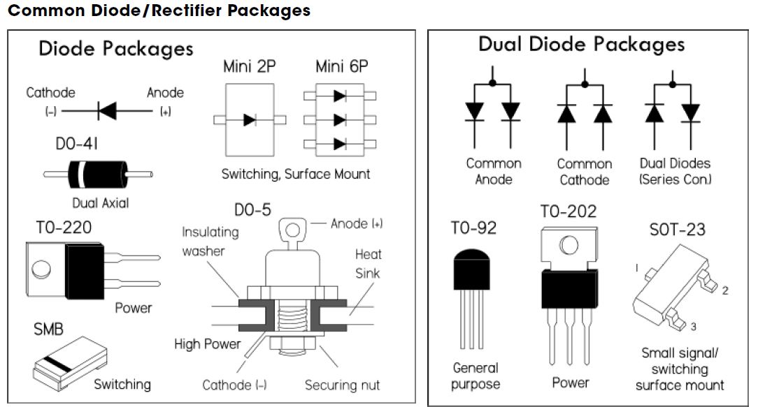
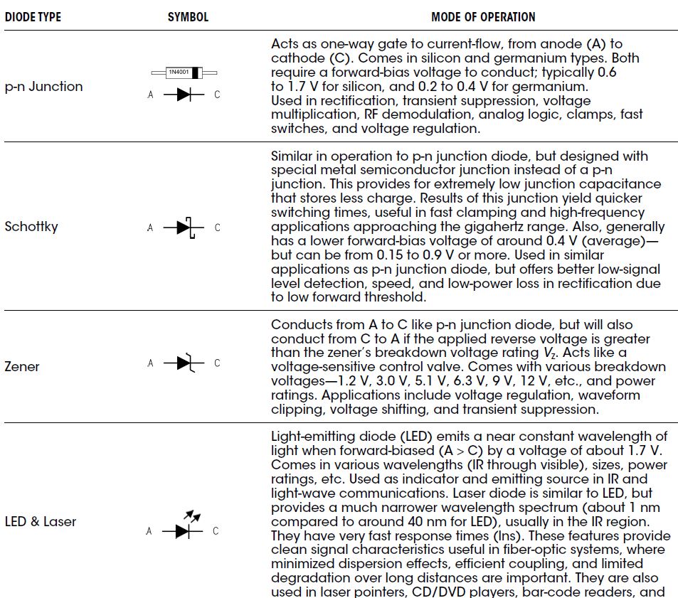
### Diodes
- Diode: is a two-semiconductor device that acts as a one-waygate to electric current flow
- Mechanism:
- "OPEN DOOR": when anode lead more positive in Voltagethan the the cathode lead ==> "forward biasing" and current is permitted to flow through the device
- "CLOSED DOOR": opposite phenomenon: "reversed biasing"
- Diode Water Analogy:
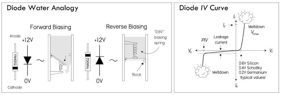
- A diode (or rectifier) acts as a one- way gate to current flow—see the water analogy in
- current flows in the direction of the arrow, from anode (+) to cathode (−),
- "forward voltage" VF across it exceeds what’s called the "junction threshold voltage"
- For example: germanium diodes have a 0.2- V threshold, and Schottky diodes a 0.4- V threshold.
- real- life components may be a few tenths of a volt off
- Check IV curve for limits:
- IF: forward current
- Io: peak current rating
- PIV: peak inverse voltage
- A very nice tutorial from Sparkfun on Diodes:
https://learn.sparkfun.com/tutorials/diodes
### Capacitors
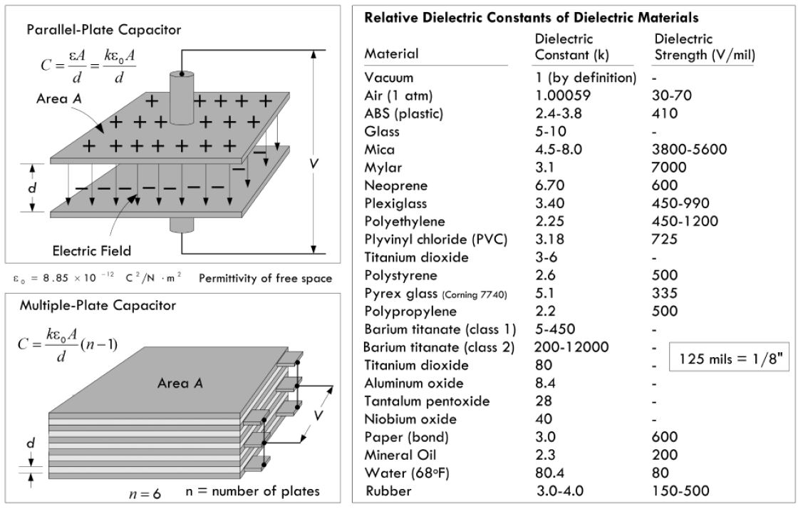
- ####basic concept
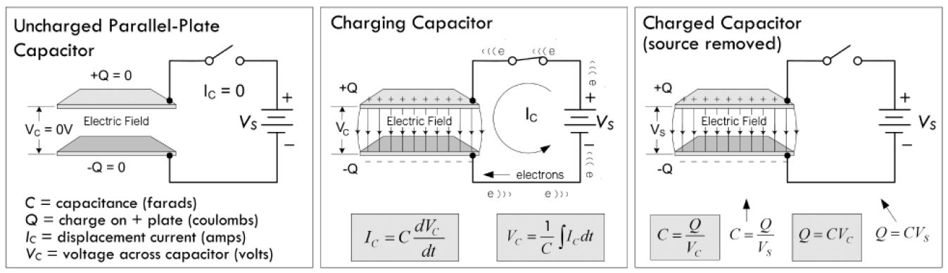
- ####Capacitance: the ratio of charge on one of the plates of a capacitor to the voltage that exists between the plates
C = Q/V, Units: Farads, 1F = 1C/1V
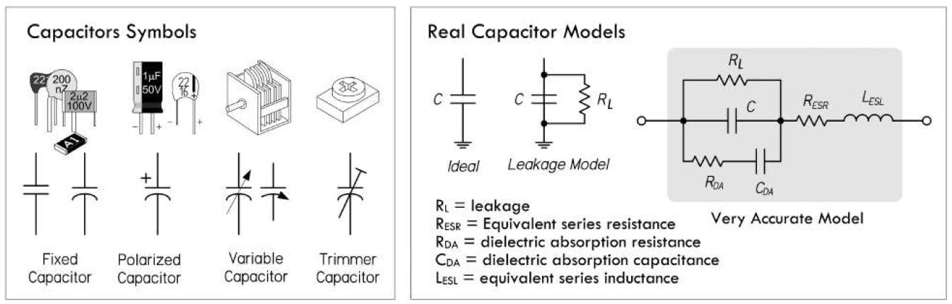
- we could be content with this limited knowledge. However, if you want
- to build your own capacitors
- understand time-dependent behavior such as displacement current and capacitive reactance
- a deeper understanding of capacitance is needed:
- A very nice Sparkfun tutorial on capacitors and their applicaitons:
https://learn.sparkfun.com/tutorials/capacitors/introduction
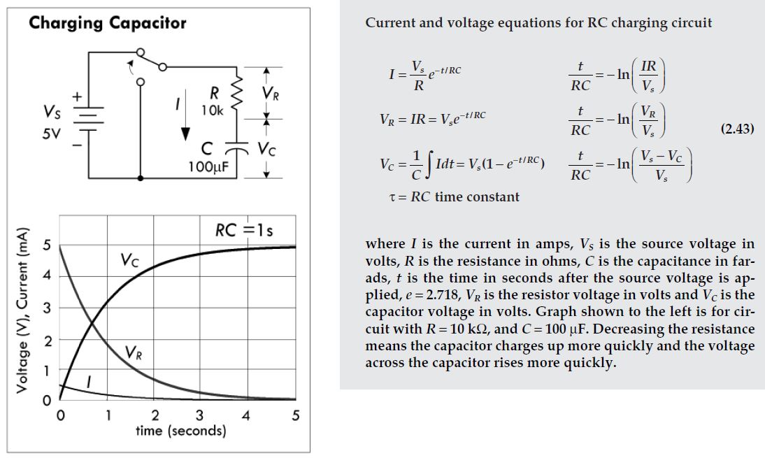
- ####RC time constant. Time domain behavior.
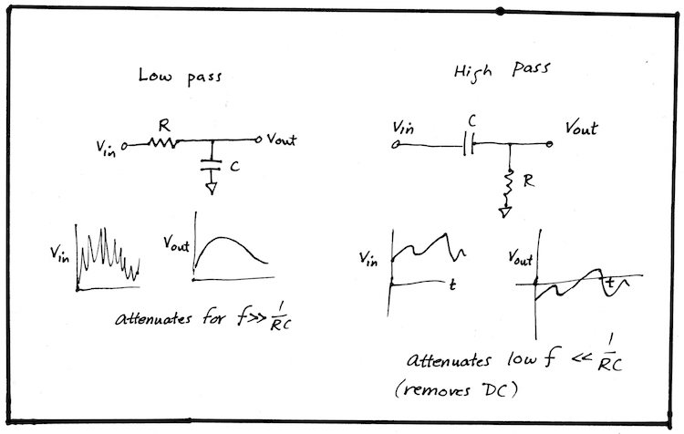
- ####Capacitors in filters: low pass and high pass.
The charging and discharging of the RC combination makes capacitors useful as frequency filters.
Discussion of symbol for ground used in the circuits below.
---
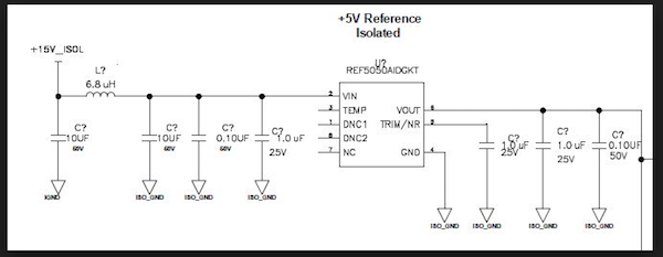
- ####filter capacitors on power rails.
Capacitors resist changes in voltage by virtue of their energy-storage capabilities.
We use them to absorb fluctuations in power supply voltage in almost every board that we make.
---
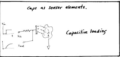
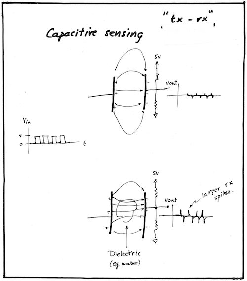
- ####using capacitors as sensors
Capacitance sensing is used in many ways. During our "Input devices" week, you will see practical examples of this.
---
### Transistors
- semiconductor devices often hidden deep within the die of an integrated circuit
- control current flow in a way similar to the way a faucet controls the flow of the water
- 2 Major Ctaegories:
- Bipolar Transistorsv (BTs)
- Field-Effect transistors (FETs)
- Major Difference:
- BTs rewuire input current at their control leads
- FETs require only a voltage
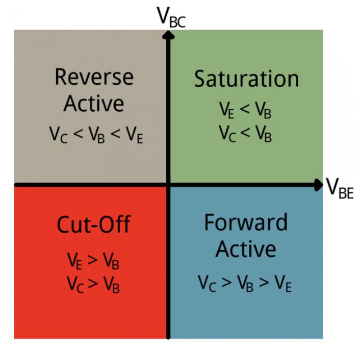
#### BTs
- 3 terminal devices that can act:
- switches
- amplifier controls
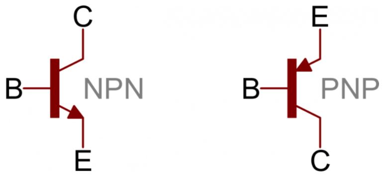
- On a bi-polar junction transistor (BJT), those pins are labeled collector (C), base (B), and emitter (E). The circuit symbols for both the NPN and PNP BJT are below:
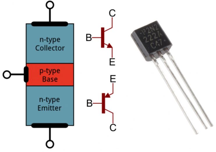
- 2 configurations:
- The only difference between an NPN and PNP is the direction of the arrow on the base. The arrow on an NPN points out, and on the PNP it points in
- NPN (Not-Pointing-In): small input current and positive V (relatiuve its emmiter) at its base to control a much larger collector-to-emmiter current
- PNP: small output base current and negative base V (relative its emmiter) to control a larger emmiter-to-collector current
- Extending the water analogy
- On – Short Circuit
- Off – Open Circuit
- Linear Flow Control
- Unsurprisingly, the water analogy can be extended to transistors as well: a transistor is like a water valve – a mechanism we can use to control the flow rate.


- Modes:
- A nice tutorial on BJTs from Sparkfun:
https://learn.sparkfun.com/tutorials/transistors#applications-i-switches
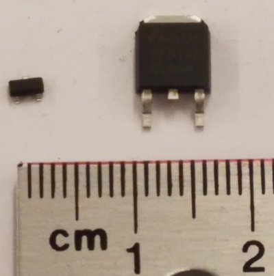
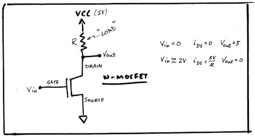
#### FETs
- Field Effect Transistors. [Article](https://www.electronics-notes.com/articles/electronic_components/fet-field-effect-transistor/what-is-a-fet-types-overview.php)
A small voltage on the input, requiring essentially no current, controls a large current through the transistor.
- Below are two of the FETs in the fab inventory. Both n-type MOSFETS. Left 1.7 amps, right 16 amps max. current. We also have p-type MOSFETS.
####Relays
- Controlling high voltage power devices using transistors:
https://www.instructables.com/id/Arduino-Tutorial-Handling-High-Power-Devices/
---